7. Audio out
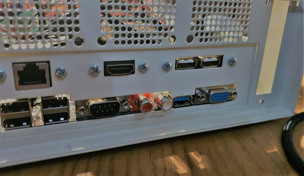
As discussed previously, there are dedicated analogue and digital audio outputs on the MiSTix board. There is a third option: audio can be output over HDMI. So the question is, which to use?
In my office all of my audio passes to my speakers through a small digital amplifier (an SMSL Q5 Pro, if you are interested). In general, I would prefer to do my digital-to-analogue conversion outside of a noisy computer case. My only way of putting HDMI audio into my amp is via a cheap and nasty inline audio extractor box. I’m therefore drawn to the digital SPDIF output on the board by default.
There is however, a big problem! The SPDIF port was not on the MiSTix prototype board which the board designer (Edu Arana) sent to the case creator (Stephen Jones) , and so was not accounted for in the case design.

In the image above we see the problem. Here the MiSTix board is mounted in the case along with its mounting kit which provides the back plate. The SPDIF port is not visible: it is to the right of the blue VGA port here and so is behind the mounting plate. So we just get the junior hacksaw out and cut a little hole for it, right? Unfortunately, not as simple as that.

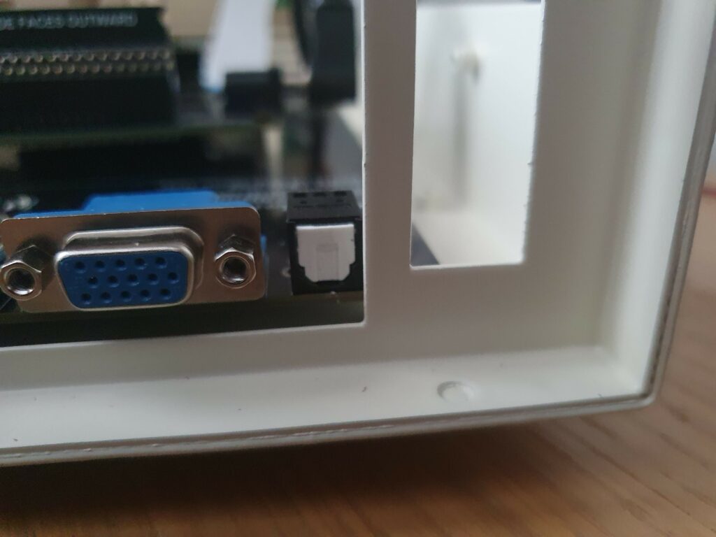
Problem number one is illustrated above. Here the board is mounted in the case without the mounting kit back plate installed. We can see and access the SPDIF port, but its really close to the actual case itself. If I put the right optical cable in, I can make the connection, but it’s at an angle. I didn’t like it at all; it’s putting pressure on the connector and the solder joints. So to make this work properly, I would have to carve a little notch out of the case itself, as well as modify the back plate.

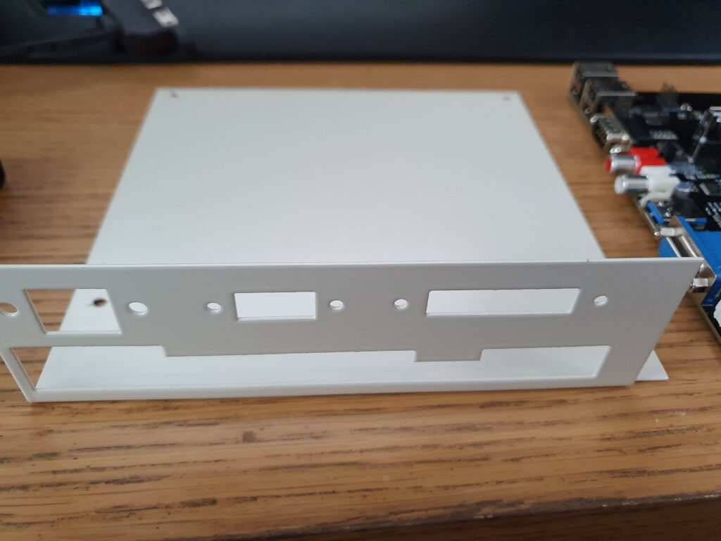
Now that we understand that, we can see problem number two if we look at the mounting frame. To accommodate the SPDIF connector where it is, I would have to cut all the way through the section of the back plate on the lower right. This would completely destroy the integrity of the frame: the top half of the back plate would be held up solely by the tiny bit of metal on the left.
I thought long and hard about how to modify the backplate and case appropriately, and concluded there was no solution that wouldn’t look and feel really messy. So plan B. If I can’t modify the case, I’ll modify the board. I desoldered the SPDIF port from the board and replaced it with a three pin header. There is a vacant expansion slot to the side of the board (you can see it in the top image) and the idea was that I would 3D print a cover for this slot with an mount for the SPDIF socket, and move it over there.
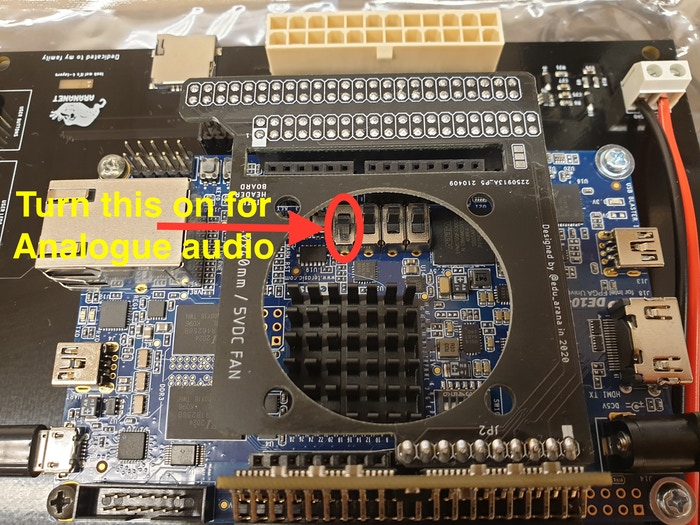
So far I have not done this, due to two things which became apparent during the build. Number one, and most importantly, the audio from the analogue ports on the board sound really good. Certainly to my ears: nice clean sound, and I can’t see how switching to the digital output would be better. Secondly, it was revealed that the digital and analogue outputs from the board are an either/or situation. To change between outputs you need to physically flip a switch on the DE10 which disables one and enables the other.

This was something of a minor disappointment. It’s a small thing I know, but I don’t like the idea of having dead ports on my spiffy new machine. I like the versatility of having both options, and I don’t want to open the case to switch between the two. So given that I was getting along fine with the analogue sound and I had plenty of more things to do, I shunted the digital output onto the back burner. Since then I’ve been happily using the board with the analogue output, and I’ve had no motivation to go back in and connect up the digital option. It’s nice to know I put that three pin header in though, so this is something I can easily go back and do at some point without taking the whole thing apart.
So, with the sound dealt with and the board and back plate now finally mounted, let’s start thinking internals!